STEP 1
At
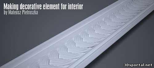
first we have to find reference image. In this case I needed to model
object I have had physically in my hands, so using scanner was an
obvious choice. After few minutes image was ready. It was too bright to
use it, so I had to darken it a little bit in photoshop to get better
contrast. Here is a final result –
download B-9.jpg image. So – after this introduction it is time to open max.
STEP 2I
will be using Generic units, so I prefer you use it as well to avoid
mistakes. Just roll out Customize from toolbar, click on Units Setup
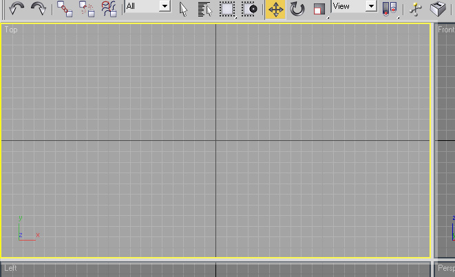
and check Generic Units. We get to the Top view – as we have view from
the top of element (you can use either of viewports but it will be
harder to operate camera in perspective then)
STEP 3
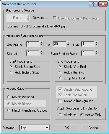
Pressing
Alt + B opens window called Viewport Background . If you think we will
choose file now, you are right. Press Files... and choose B-9.jpg in
this case. Then tick Match Bitmap, Display Background, Lock Zoom/Pan –
it will allow us to use image as a blueprint.
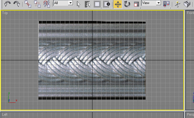
Press OK. It should look like this:
STEP 4
As
you can see in the viewport in this situation grid is rather annoying,
so I prefer turning it off (just press G as the Top view selected). Now
we get into modeling. First step is to create Cylinder with parameters
– radius 7.5 and height 164 with eg. 12 height segments. Place it like
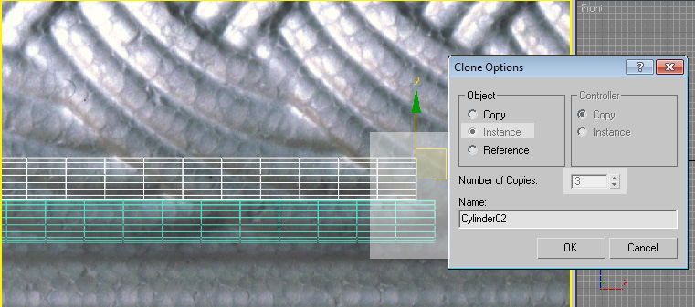
shown on the image below. Clone it 3 times. Just hold Shift and move it
like shown in picture. It is important to have Gizmo correctly in this
place (just create Cylinder from Left view).
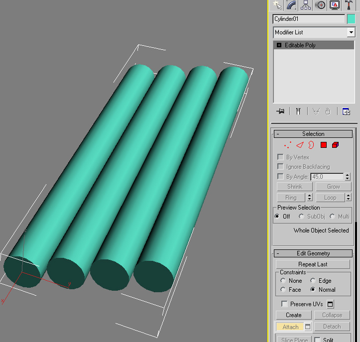
STEP 5 Now bending it. Convert one Cylinder to Editable Poly and then use Attach button to attach all these objects in one.
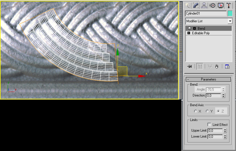
STEP 6
We have them attached. It is time to add Bend modifier from Modifier
List. Angle parameter allows us to control value of bending it. As you
can see -70.5 does its job. It will disturb somehow our placement, so
move it again into correct position (even turn it a little bit to match
the reference).
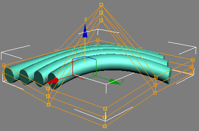
STEP 7
Now, also from Modifier List, choose FDD 3x3x3. Roll it out and click
on Control Points. Select middle points and put it higher than others.
After doing it, select the others two on the one edge, and put it
lower, like on the screenshot. It is necessary to avoid bad collisions
in future.
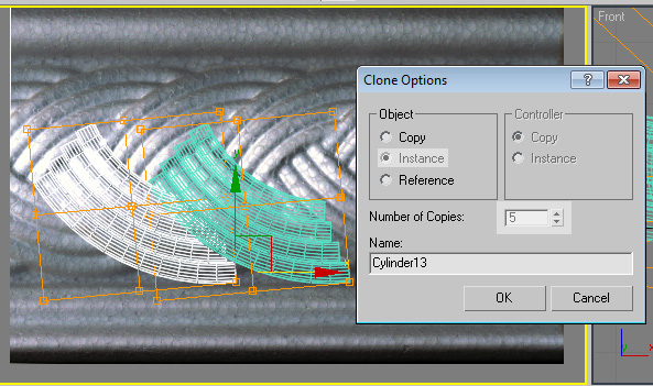
STEP 8
We are ready to clone our model. Like before, hold shift and move it
like on the picture. Now we just clone it 5 times just for training (if
you want you can clone it 1 000 000 times – amount does not matters).
Remember to be even though a little bit precise to match the reference.
Check Instance – if you would like to change shape or bending value,
changing it just in one random element will cause changes in every
object.
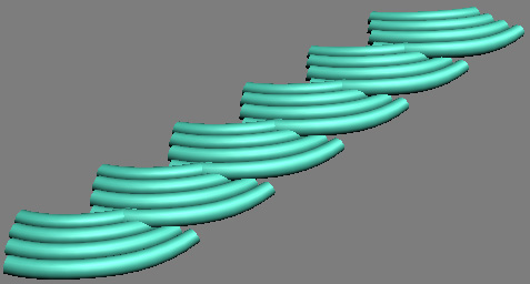
And as a result of our work, we should get something similar to this:
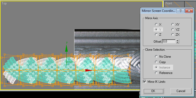
STEP 9
We have done just one side. It is time to do the second one – very easy
and fast method. Select all of the elements and click on the Mirror
icon on the command panel.
New windows appeard – just make everything look like on the screenshot below.
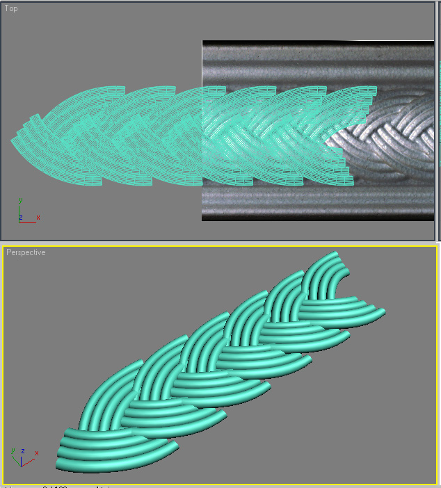
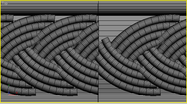
STEP 10
We get a little bit confused element, so it is time to put it in some
order. Just move it to match the reference. This is what we should get
after it:
STEP 11
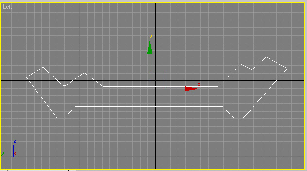
Main thing is finished. Now we will model something to put in on. I
have chosen rather simple shape. Just use Line from Splines section.
And try to achive for example this shape:
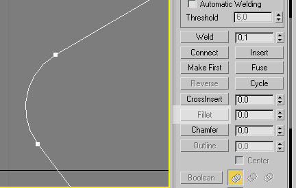
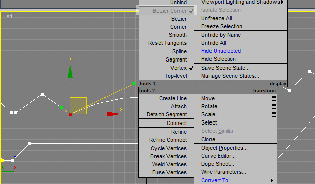
STEP 12
I use mostly Fillet to get little bends. Just select vertex where you
would like to have smooth corner, click on Fillet and insert some value
(the higher the smoother corner is) or just simply move arrow pointer
on vertex and slide it with left mouse button pressed.
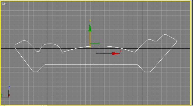
Bigger bends are easier to control with bezier and bezier corner.
After some tweakings with line, we should end up with something similar to this:
STEP 13
Now we have just a spline so it is time to make it real object. It is
very simple – just add Extrude modifier from list and enter value as
big as you like. It just controls length of element. So we are done
with it. It is time to make it fully tillable.
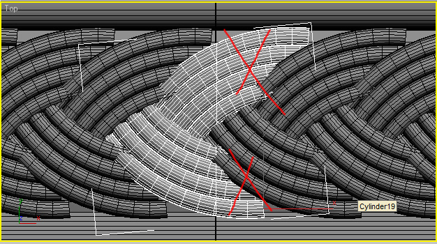
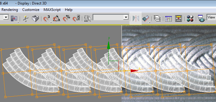
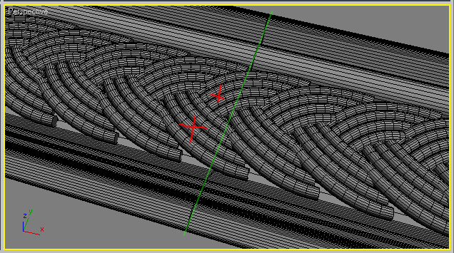
STEP 14
Select all elements in the scene, clone and move it on the right to
match excatly the ends of last element. Convert last 2 elements (with
red crosses on the screenshot) to editable poly and attach them to
themselves. We will use Quick slice (Edit geometry) to cut it fast and
without pain. Maximaze the Top view and cut it somewhere where the line
on the picture appears (it is end of last element we have created with
line). Try to be precise to cut it perpendicular as it is possible.
It will add new vertixes along the cut line.
STEP 15
Now delete everything what is on the right side of the cut (crossed
with red lines). Delete also elements from the right – they were there
just to help us with matching correct position.
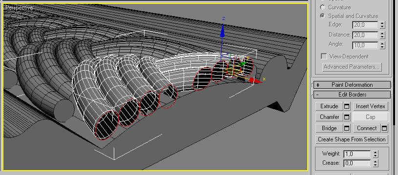
We ended up with open cylinders, so we have to close them. Use Border
to select edges and then click on Cap. It will fill the ends.
Done on the one side and for the other side is 99% the same. Copy, cut and cap. This is what we should get:
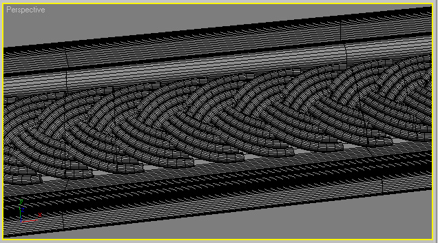
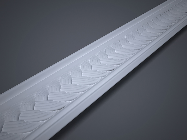
We
have nice, fully tillable decorative element for our interior. It has
many polys but you can easy change it just by lowering down segments or
sides, thanks to instance copying. Final result after rendering is
right here:
Source:www.evermotion.org